Region Convert for Tesla Model 3: US to Europe Modem Upgrade Guide
Experiencing connectivity issues with your imported US Tesla Model 3 in Europe? You’re not alone. Many owners face challenges due to incompatible LTE modems. While importing a Tesla Model 3 from the US to Europe can be a fantastic way to get a great deal on a used electric vehicle, the difference in LTE network frequencies between the US and Europe can lead to significantly reduced mobile data speeds – often dropping to frustratingly slow EDGE connectivity. This article provides a comprehensive guide on how to perform a region conversion for your Tesla Model 3 by upgrading the modem from the US version to a European compatible one. We’ll delve into the process of replacing the original modem with a European counterpart, ensuring your Tesla regains optimal LTE performance on European networks.
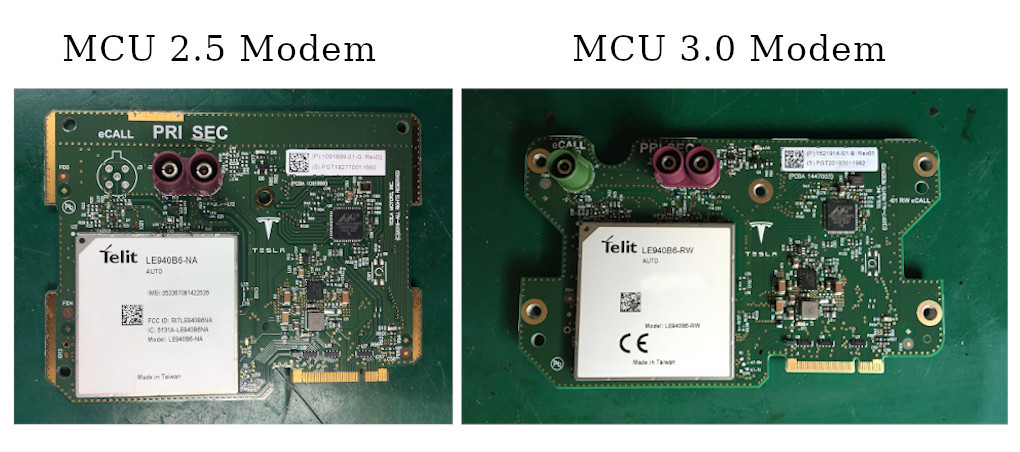
The Tesla Model 3’s communication system relies on a dedicated modem board, integrated within the car’s Media Control Unit (MCU). While details for Model S and Model X may vary, the Model 3 primarily uses two MCU versions: MCU 2.5 (used in 2018-2019 models) and MCU 3.0 (introduced in 2019 onwards). This upgrade guide focuses on both MCU versions, highlighting the subtle but important differences in modem compatibility. Fortunately, the MCU 3.0 modem design is largely backward compatible with MCU 2.5, simplifying the upgrade process.
Tesla Modems Comparison: MCU 2.5 vs MCU 3.0 showing compatibility and design differences
Caption: A visual comparison of Tesla modems for MCU 2.5 and MCU 3.0, illustrating design similarities and cross-compatibility.
While European modems generally follow the 3.0 style design, a crucial distinction exists between US and European versions: the eCall connector. European regulations mandate eCall, an emergency call system, which necessitates a specific connector absent in US modems and, consequently, the US MCU casing. While some have resorted to drilling into the MCU cover to accommodate this, a cleaner and often preferred solution is to remove the eCall connector from the European modem altogether, as it is not functional or required when retrofitting to a US-spec car.
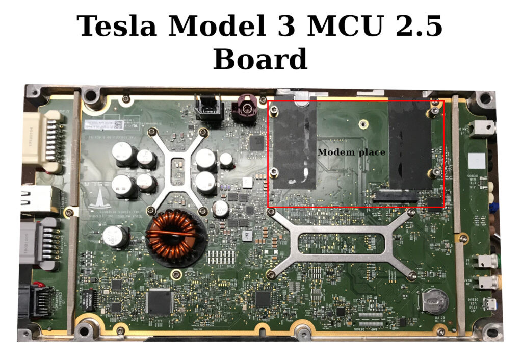 Tesla Model 3 MCU 2.5 highlighting the modem location and design
Caption: Close-up view of a Tesla Model 3 MCU 2.5 unit, pinpointing the modem module and its integration within the system.
Understanding the Tesla Modem
The heart of the Tesla modem is a sophisticated integrated module from Telit, a leading provider of IoT modules. Tesla employs different Telit modem models tailored for specific regional market requirements, primarily to support varying LTE frequency bands.
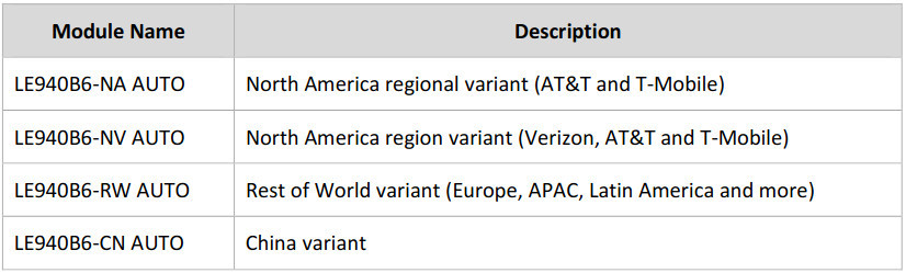 Tesla Model 3 Modem Versions showcasing different regional variants
Caption: An overview of different Tesla Model 3 modem versions designed for various global regions and network compatibility.
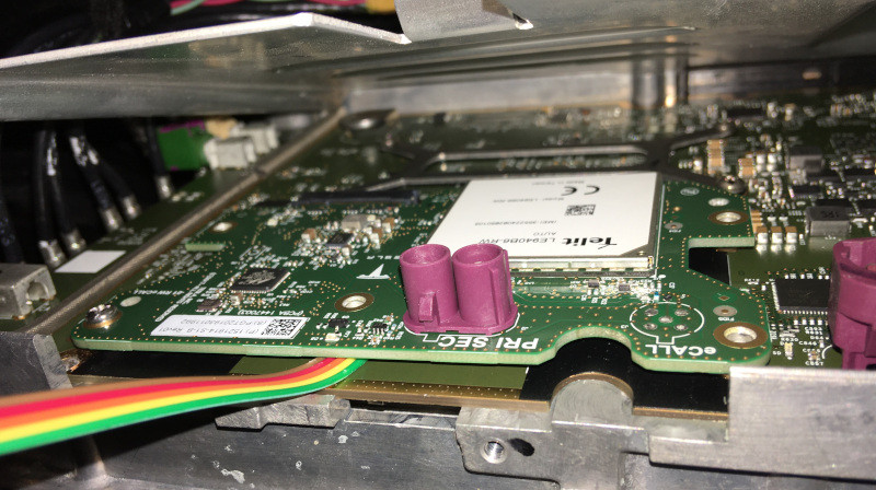
Let’s dissect the key components of the modem board to understand its functionality.
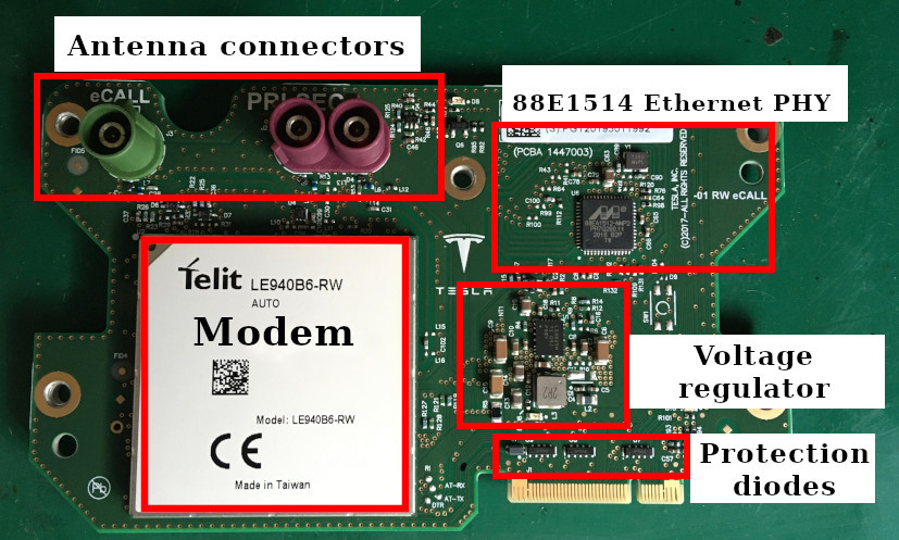 Tesla Model 3 Modem Overview highlighting key components like Ethernet PHY and Telit module
Caption: Detailed component layout of the Tesla Model 3 modem board, identifying the Ethernet PHY, voltage regulator, and Telit module.
The prominent 88EA1514 chip is an automotive-grade version of the Marvell 88E1514 “Alaska” Ethernet PHY. This crucial component manages data communication between the modem and the MCU, facilitating internet connectivity. Interestingly, Tesla utilizes a Serial Gigabit Media Independent Interface (SGMII) instead of standard Ethernet, leveraging the SerDes capabilities of the 88EA1514 for efficient data transfer over SGMII pairs to the MCU board.
Power regulation is handled by the automotive-qualified LM53625 voltage regulator from Texas Instruments. This regulator is configured to deliver a precise 3.8 volts, the specific voltage demanded by the Telit module for optimal operation.
The Telit module itself is a powerful, self-contained system on a chip (SoC), functioning almost as a mini-computer within the modem. It runs its own operating system and exposes a range of interfaces. Tesla primarily utilizes Ethernet for high-speed data, UART for AT command communication (likely for diagnostics and control), and various control signals for managing the modem’s operation. The audio interface on the Telit module is likely not utilized in this Tesla application.
Removing the EMI shield reveals the core processing and memory components of the Telit module:
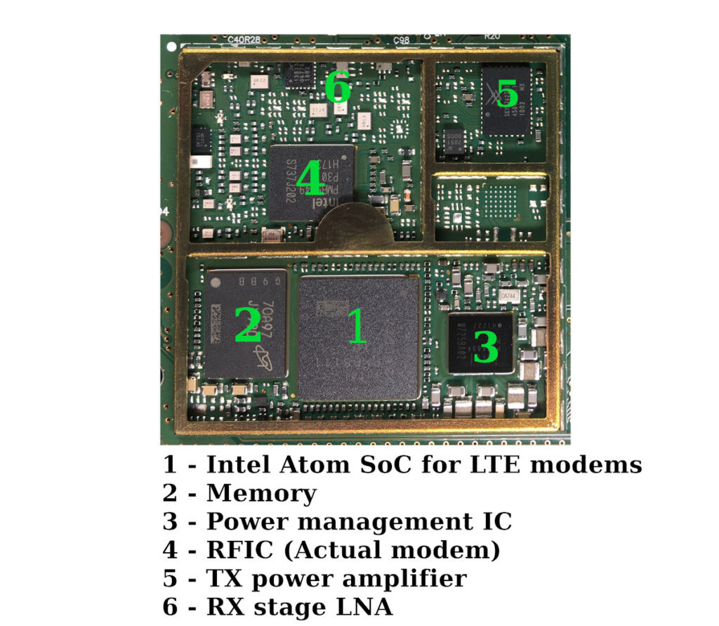 Telit Modem ICs showcasing the internal chips and components within the module
Caption: Internal view of the Telit modem module, exposing the integrated circuits and processing units that manage cellular communication.
Intriguingly, Tesla employs an eSIM (embedded SIM) for connectivity. However, under the hood, this eSIM is essentially a standard SIM card permanently soldered into an IC package.
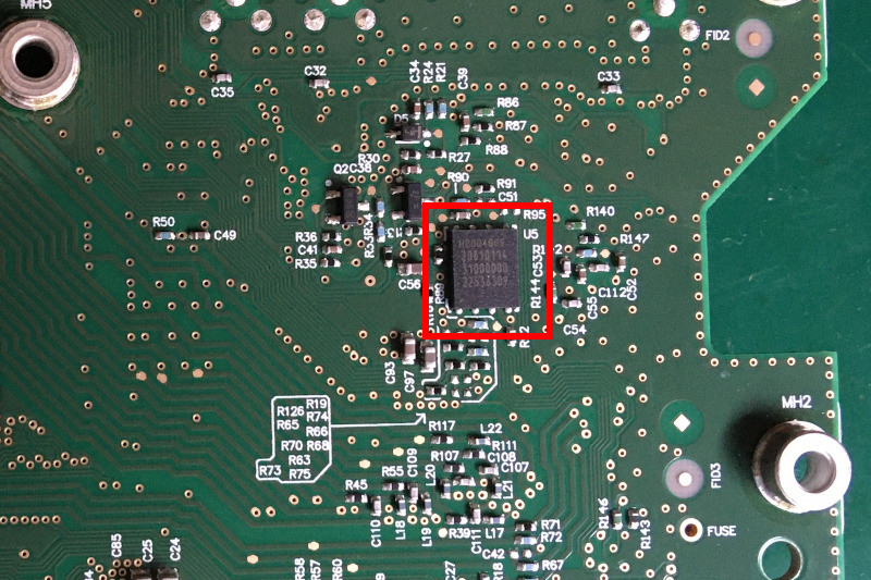 Tesla LTE Modem eSIM showing the embedded SIM chip and its integration
Caption: Close-up image of the Tesla LTE modem’s eSIM, highlighting the embedded SIM chip and its connection points.
This eSIM contains a unique phone number pre-programmed and associated with each Tesla vehicle. Tesla leverages this eSIM for remote vehicle wake-up via SMS commands when accessing car functions through the mobile app, as well as for managing mobile internet data subscriptions.
The Tesla modem is undoubtedly a sophisticated piece of technology, ripe for further exploration and reverse engineering. Future articles may delve deeper into its intricacies. For now, let’s focus on the practical steps for modem replacement to enable European LTE compatibility.
Preparing the European Modem for Installation
The initial step in the modem conversion process is adapting the European modem to accept a standard, readily available SIM card from a local European mobile operator. The factory-installed eSIM needs to be replaced.
Removing the eSIM chip is a straightforward process using a hot air rework station and a touch of flux to aid in desoldering the chip from the board.
Once the eSIM is removed, a standard SIM card can be connected directly to the eSIM pads on the modem PCB. The following wiring diagram illustrates the pin mapping for a direct SIM card connection:
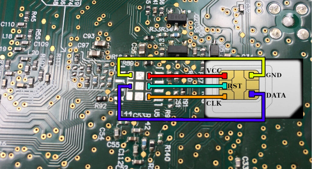 Tesla Modem SIM Wiring Diagram detailing the pin connections for standard SIM card integration
Caption: Wiring diagram illustrating the pin connections required to interface a standard SIM card with the Tesla modem after eSIM removal.
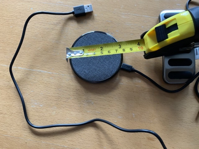
For a more user-friendly and accessible solution, creating a SIM card extension cable with a standard SIM card holder is highly recommended. This allows for external SIM card access without needing to disassemble the MCU in the future.
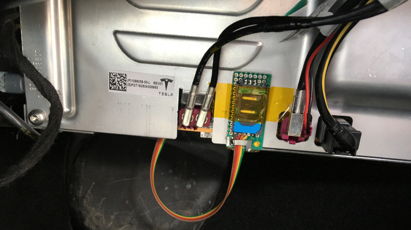
The wires for the SIM extender are carefully soldered to the eSIM pads and secured with a combination of hot glue and Kapton tape for robust insulation and strain relief. With the SIM extender prepared, the European modem is ready for physical installation.
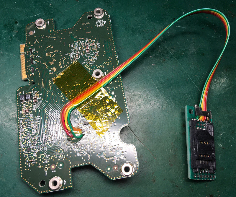 Tesla Modem SIM Extender Connected showcasing the prepared modem with external SIM access
Caption: Image of the European Tesla modem with the SIM card extender cable connected, providing external access to the SIM card slot.
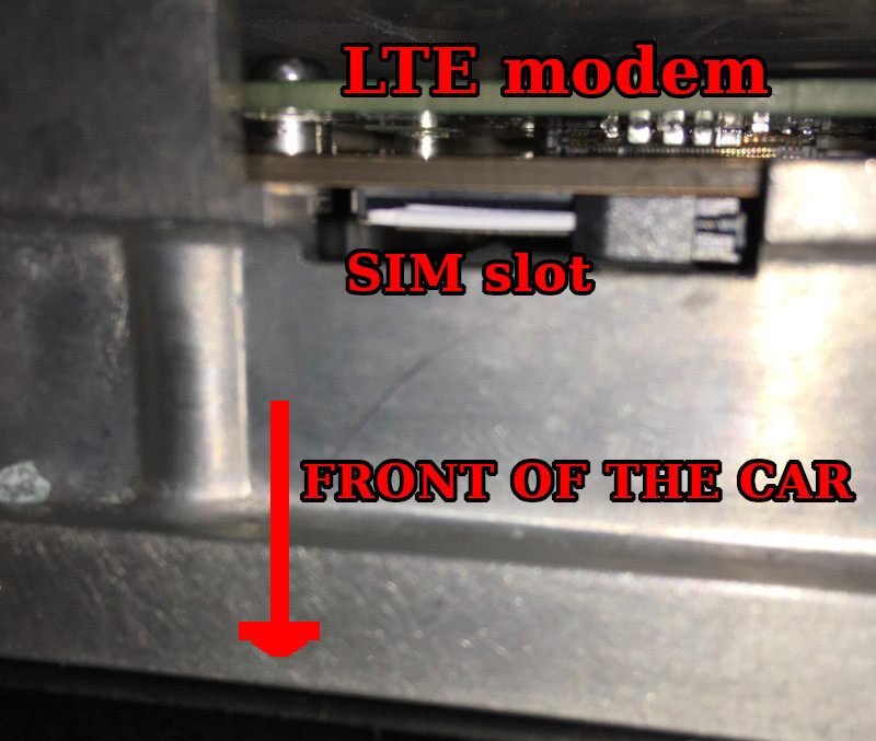 Tesla MCU SIM Slot highlighting the onboard SIM card reader
Caption: Close-up view of the Tesla MCU’s onboard SIM card slot, indicating an alternative SIM card input option.
It’s important to note that the Tesla MCU also features a physical SIM card slot directly on the mainboard. In certain software configurations, this slot can be utilized instead of the eSIM. The SIM card is inserted into this slot with the cut corner oriented upwards, pushing it in until it clicks into place. To remove the SIM card from this slot, simply push inwards again with a small tool, like a plastic trim removal tool.
The active SIM card configuration (eSIM vs. physical SIM slot) is managed through Tesla’s proprietary diagnostic tool, known as “Toolbox.” Originally a standalone desktop application, it has transitioned to a web-based service. Further details regarding Toolbox operation are beyond the scope of this article.
Installing the European Modem in Your Tesla Model 3
Before commencing any hardware modifications, it’s crucial to ensure the vehicle is completely powered down. Navigate to the Tesla touchscreen menu: ‘Safety & Security’ and select ‘Power Off’. After initiating the power down sequence, avoid touching any pedals, buttons, or the touchscreen. For safety, lower all windows and leave both front doors slightly ajar. Closing the doors after shutdown can make re-entry challenging.
Next, access the front trunk (frunk), remove the plastic cover near the windshield, and disconnect the negative terminal of the 12-Volt auxiliary battery.
For added safety, and as recommended for working on the MCU, proceed to remove the rear passenger seat bench. Lift the bench upwards to detach it and then disconnect the high-voltage battery service disconnect located underneath.
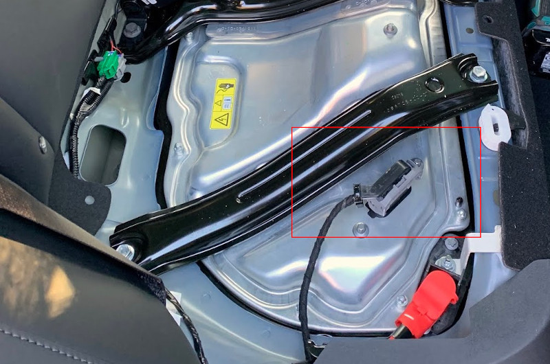 Tesla 400V Battery Disconnect showing the location of the high voltage disconnect under the rear seat
Caption: Location of the Tesla Model 3 high-voltage battery disconnect service loop, situated beneath the rear passenger seat.
Accessing the MCU requires removing the front passenger airbag and the glove box assembly. Unfortunately, detailed photographic documentation of this specific step is limited.
Start by locating the plastic trim panel at the lower section of the glove box. This panel, which incorporates ventilation and lighting, is secured by four plastic clips. These clips can be carefully released using a trim tool or tweezers. Positioned above this plastic panel is the passenger knee airbag – a substantial plastic and metal component fastened by two self-tapping screws and four 8mm bolts. Support the airbag panel while removing these fasteners to prevent it from dropping. Once detached, gently disconnect the two-wire airbag electrical connector.
The glove box itself is secured by five self-tapping screws. One screw is concealed beneath a small plastic cover on the right side of the glove box opening, and the remaining four are located under the top decorative trim panel, accessible when the glove box is opened. Unscrew these fasteners and carefully pull the entire glove box assembly outwards. Be mindful of two wiring harnesses connected to the glove box – disconnect these before fully removing it.
With the glove box removed, proceed to the exterior of the vehicle. Locate four nuts positioned at the front left side of the car, under the hood, near the base of the windshield. Loosen these nuts, but do not completely remove them. These nuts secure the MCU enclosure.
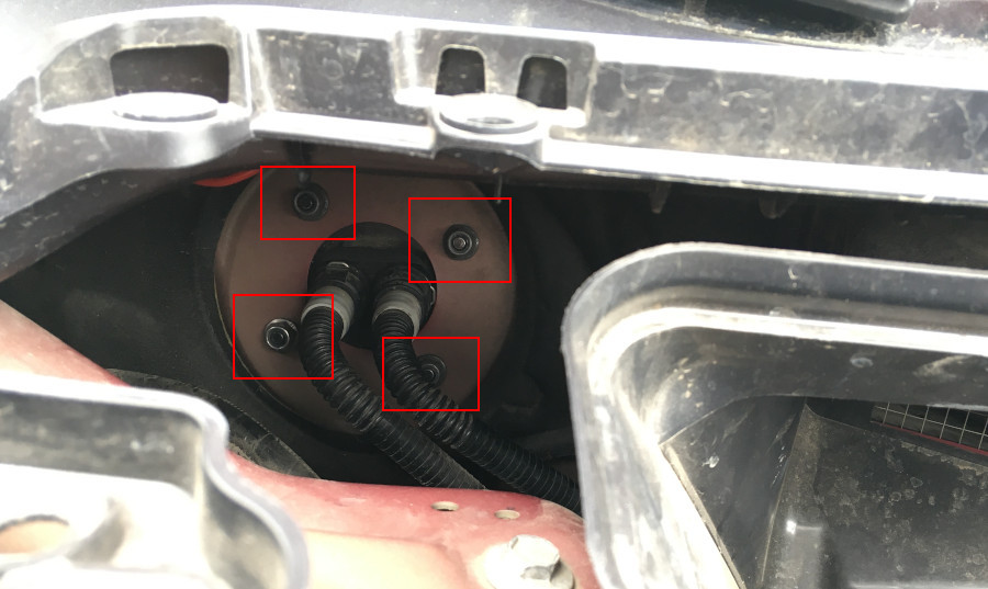 Tesla MCU Screws indicating the location of the nuts securing the MCU unit
Caption: Location of the four nuts under the hood that secure the Tesla Model 3 Media Control Unit (MCU) enclosure.
The MCU is now relatively accessible.
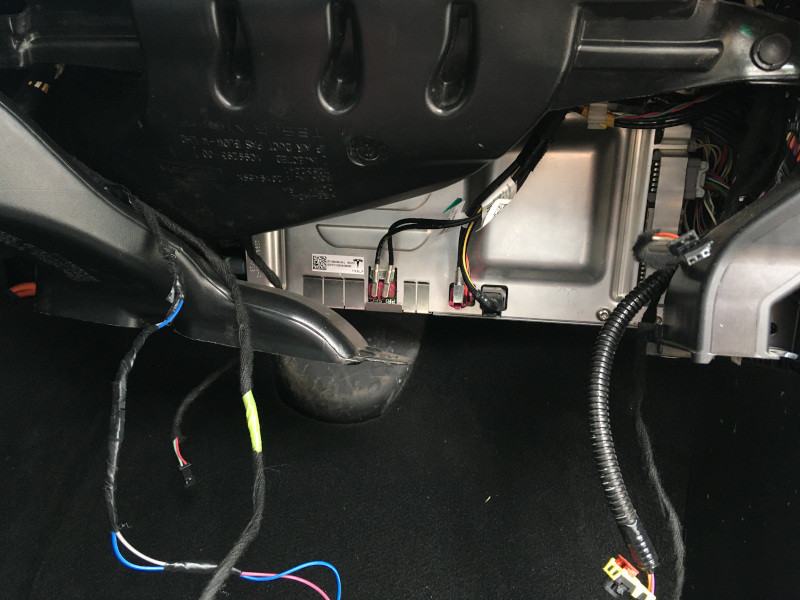 Tesla MCU Reveal exposing the MCU unit after glovebox removal
Caption: The Tesla Model 3 MCU unit exposed after removing the glove box assembly, ready for modem access and replacement.
Removing the original MCU 2.5 modem is straightforward. Simply unscrew the single screw securing the modem’s metal bracket and gently pull the modem downwards, similar to removing an expansion card from a computer motherboard.
For MCU 3.0, accessing the modem requires unscrewing the aluminum top cover of the MCU enclosure. At least the bottom portion of the cover needs to be detached – don’t hesitate to carefully bend the cover if necessary. The aluminum cover must be at least partially removed to facilitate the installation of the new modem.
Install the new European modem by pushing it firmly into the modem slot. Secure it with at least two screws to ensure a stable connection.
 Tesla New Modem Installed showing the European modem in place within the MCU
Caption: The new European modem securely installed in the Tesla Model 3 MCU, replacing the original US modem for regional LTE compatibility.
Position the SIM card holder from your extender cable on the MCU’s aluminum cover or a convenient nearby location. This placement ensures easy access to the SIM card without requiring extensive disassembly in the future.
 Tesla MCU and SIM Holder demonstrating the external SIM holder placement for accessibility
Caption: The Tesla MCU with the external SIM card holder mounted for easy access to the SIM card after the modem upgrade.
Reassemble all components in reverse order of disassembly. Reconnect the batteries, starting with the high voltage battery service disconnect, then the 12V negative terminal. Once everything is reconnected, press the brake pedal to initiate the MCU boot-up sequence. The MCU should power on within approximately 30 seconds. LTE connectivity should become available within a minute or two after boot-up.
Congratulations! You’ve successfully completed the region conversion for your Tesla Model 3 modem. Enjoy significantly improved LTE speeds and seamless connectivity in Europe.
Thank you for reading!